Power Electronics
Different levels of details and complexity may be used for the modelling of power electronic systems. Portunus offers ideal means for many of the possible applications. In addition to the standard functions and interfaces of Portunus, the user may choose from many predefined models and parameter sets available in the “Power Electronics Library”.
The special challenges in the simulation of power electronic systems are caused by the extremely different time constants and the resulting need for a simplification of the component and control models. In turn, these simplifications require special functionalities of the simulator.
The versatile modelling means available in Portunus and the simulator that uses a variable step size provide an excellent starting point for efficient power electronics simulations. Components may be modelled by “switch models” (using characteristics or as entirely ideal switches), by detailed networks (e.g. manufacturer models written in SPICE or VHDL-AMS) or by a combination of both approaches. Unlike several other simulators, Portunus won’t run into convergence problems because of the square-wave voltage waveforms generated by the ideal switches.
Generation of control signals can be done in different ways.
- The “Power Electronics Library” contains ready models for many standard algorithms.
- A simple way of graphical logic modelling is the editing of a state machine. Typically, every component of the state machine is linked with a switching state of the power electronic system. Transitions between the states can be triggered by timers or by a comparison of reference and actual values (e.g. current band control).
- Complex control algorithms may be programmed by using the C++ programming interface. Experience has shown that structures with many conditions may be best implemented by code rather than by a graphical representation. An additional advantage of the C++ interface comes from the possibility of using at least parts of the code which is run in the real hardware.
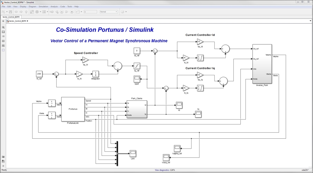
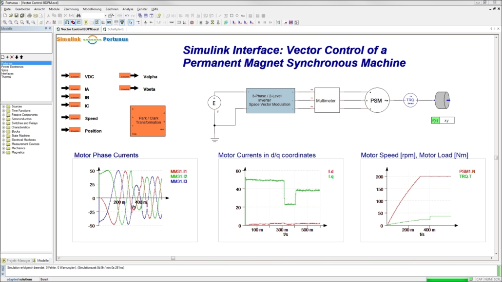
- Other alternatives for representing the control are the usage of simulator coupling, for example to Matlab®/Simulink®, or the modelling language VHDL-AMS.
Quite often the calculation of electrical values, the resulting power dissipation and the temperatures following from them should be linked. The set-up of the thermal networks and the links to the values of the electrical system can be realized easily in Portunus. A common source of difficulties is the fact that even small inaccuracies in the curves of the electrical transients lead to bigger errors in the calculation of the power dissipation. On the other hand one has to keep in mind that highly precise simulations require small step sizes which make efficient electro-thermal simulations impossible. One alternative is the usage of so-called “average models” which combine simple switch models with analytical or look-up table functions for the determination of conduction and switching losses. In cooperation with Infineon, such an average model has been developed for Portunus. More than 100 parameter sets are available for this model.
As for all other system parts, the modelling of the load present in the power electronic system may be done in different ways depending upon the application. Current sources controlled by time functions or simple networks do the job in many cases. For other applications, the models of electrical machines available in Portunus or user-defined models can be used.
Thermal Calculations
Investigation of thermal processes may be carried out in Portunus by using thermal networks. Unlike the alternative time consuming numerical methods like Finite-Element-Analysis (FEA) and computational fluid dynamics (CFD), this approach allows for short calculation times and therefore the fast determination of the temperature values that occur in steady-state or during load cycles. Parameter variations such as geometry, cooling types, etc. may also be easily analysed.
Many simulation systems use the analogy of electrical and thermal networks (temperatures – voltages, heat flow – current, thermal resistance – electrical resistance etc.) only. With the models provided in the “Thermal Library”, Portunus offers far more capabilities for the simulation of linear and non-linear heat transfer.
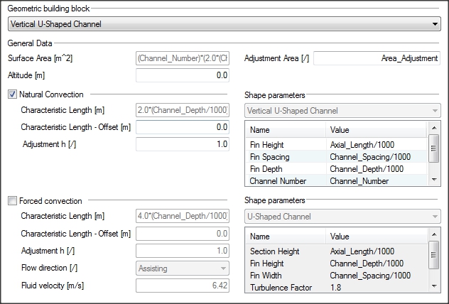
When setting up a model, the user may always choose between entering physical values (thermal resistance, thermal capacitance, Nusselt number etc.) and the input of geometry and material data. For example, the complex mechanisms of natural and forced convection are covered by a number of models related to shapes, so-called “geometric building blocks”. These models require the input of dimensions and, if necessary, the flow of the cooling liquid. Internally, these inputs are converted into parameters of the non-linear heat transfer equations, sometimes under consideration of different modes, e.g. for laminar and turbulent flow. Alternatively, more abstract models may be used where the user enters physical values like Nusselt and Rayleigh numbers directly.
Model parameterisation can be done entirely by using variables. Therefore the user may clearly specify all the dependencies. For example, heat transfer at the surface of a device works with concurrent radiation and convection. The thermal network reflects this by a parallel arrangement of the two models which are influenced by the same geometry parameters. By using the same variables in both models, consistency of parameterisation is always given.
Thermal calculations are possible for many applications. Quite often power electronic systems and electrical machines are investigated.
In power electronics, the heat transfer inside the chip is usually characterised by the manufacturer by means of the so-called Foster model. This model features a chain (serial connection) of cells where a thermal resistance and a thermal capacitance are placed in parallel. The advantage of this model is its easy parameterisation from the Zth curve. The drawback is the incorrect modelling of the heat flow into the heat sink which requires the usage of combined (adapted) chip and heat sink models. An alternative is given by the, physically correct, Cauer model which uses thermal capacitances connected to the ground node. Both models are implemented in Portunus. The parameters of the Cauer network may be calculated automatically from those of a Foster network.
Power to be dissipated may be defined by using time functions or importing system values by means of equations or graphical links (“electrical wattmeter with thermal pin”). Fast coupled electro-thermal simulations of Infineon power modules may be done with the help of a so-called “average model”. This model may either run by using a constant value of the junction temperature or in connection with a thermal network.
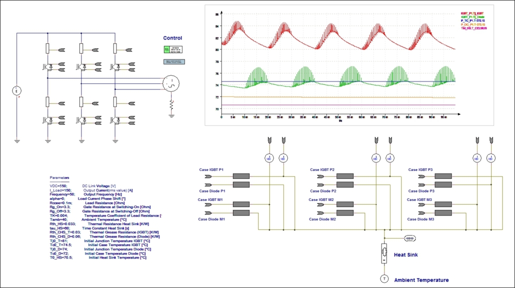
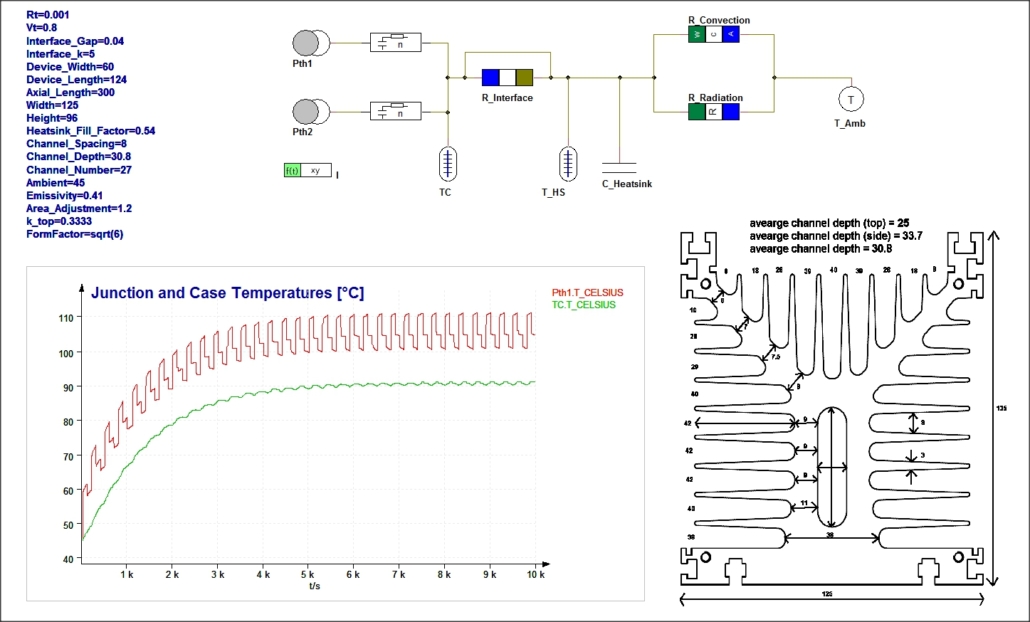
The adjacent picture shows a load cycle simulation for two rectifier diodes mounted at a heat sink. The curve of the load current is given by a time function and the losses are calculated from it depending on the diode characteristic. Heat transfer inside the chip is modelled by a Cauer network.
The heat transfer between chip and heat sink (thermal grease) and from heat sink to the ambient is modelled by using models from the “Thermal Library”. Dimension and material data of the heat sink are used for the parameterisation. The diagrams show the calculated curves of junction and heat sink temperatures. The ripple caused by the load cycle can be clearly seen in the curve of the junction temperature.
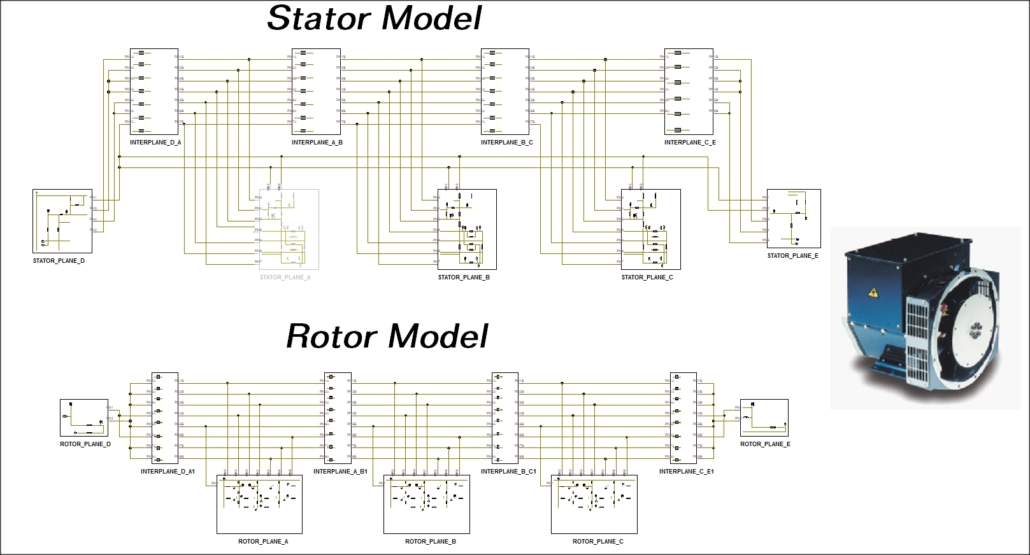
The heat flow inside electrical machines may be described by thermal networks whose structure depends heavily on the machine type, for example electrical or permanent magnet excitation, inner or outer rotor, air or water cooling, etc.. When building up models, it often makes sense to split the system into sub-systems as shown in the adjacent picture (University of Edinburgh / Cummins Generator Technologies).
The models of the “Thermal Library” support transient simulations as well as DC and operating point calculations. A transient simulation may be preceded by a DC or OP calculation in order to shorten calculation time. For switched systems, a fast calculation of steady-state values can be realised via scripts using the automation interface of Portunus.
Drives
The versatile modelling means and the interfaces available in Portunus make it possible to model drive systems using different complexity levels.
The machine models that come with the Portunus library reflect the electro-magnetic interactions in standard machines. These models allow for coupling to mechanical networks and therefore an easy modelling of the load. Machine parameters can be set via file import from Speed®.
Complex machine models or models of special machine types can be created by the user with the help of VHDL-AMS or the C++ programming interface. A coupled simulation with the software EasiMotor von EASITECH® can be run in order to carry out detailed investigations using finite element calculations.
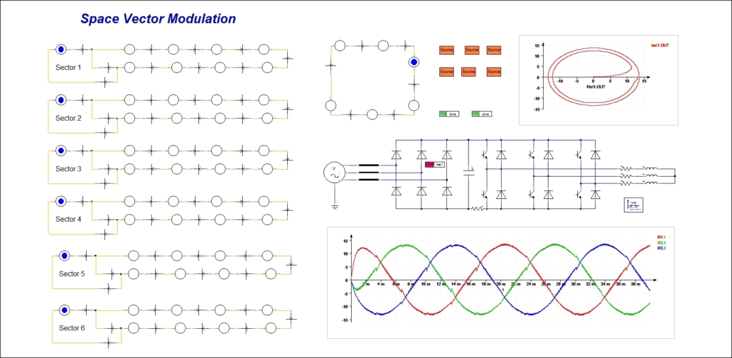
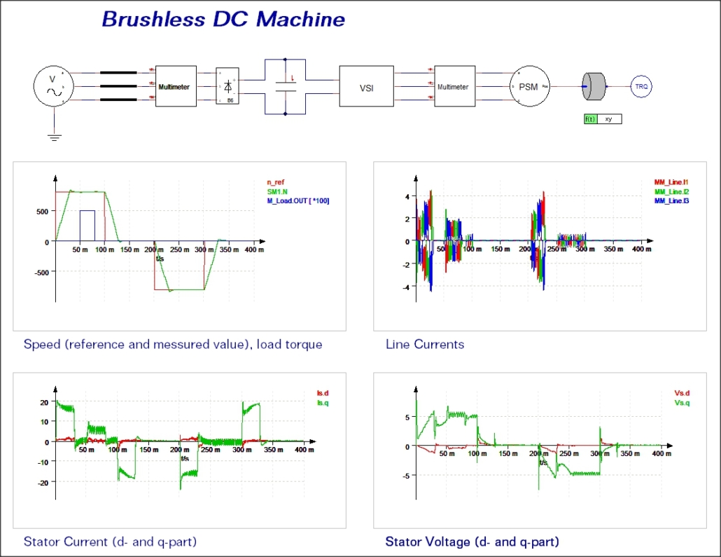
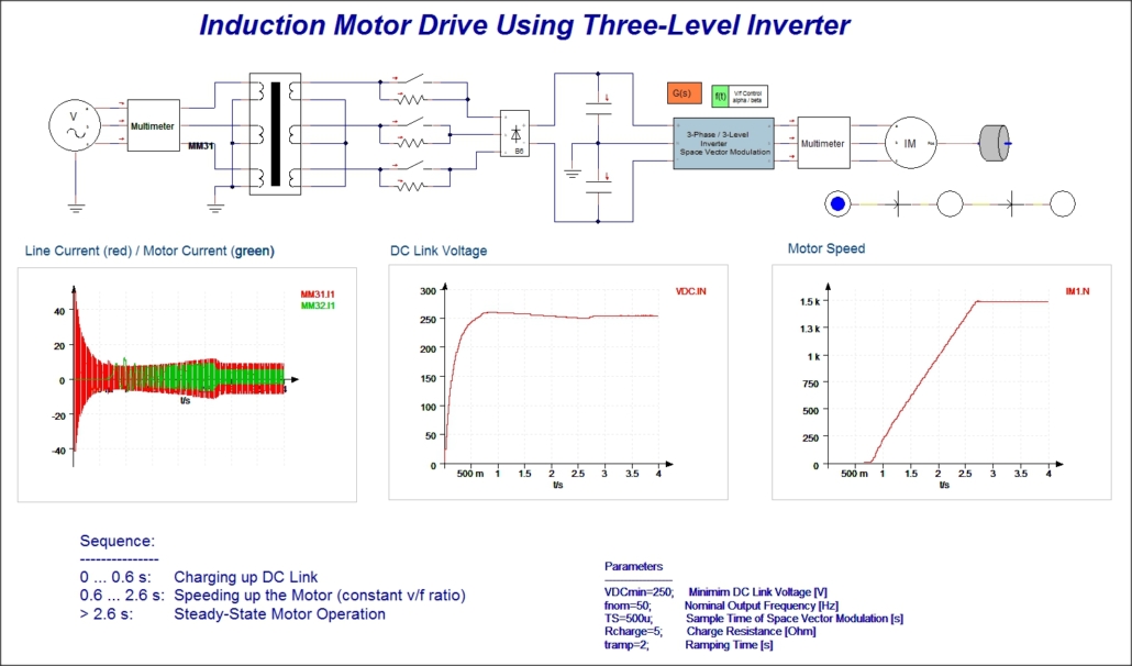
The modelling of the frequency inverter can be carried out using models from the “Power Electronics Library”. In addition to models that reflect the pulsed operation of the power electronics systems, this library contains components that use simpler approaches (voltage sources realizing the average terminal voltages) and therefore lead to shorter calculation times. Special blocks provide models for several common control algorithms (voltage-frequency control, natural sampling, space vector modulation etc.). Alternatively, the user may set up his own algorithms by using state machines, block diagrams, VHDL-AMS or the C++ programming interface. The usage of the simulator coupling to Simulink® is another alternative for the modelling of the drive control.
Simulation of drive components may include the calculation of electrical, magnetic and mechanical values but also the determination of thermal conditions. Thermal networks can be created for the power electronics components but also for electrical motors. In the latter case, parameterized networks can be imported from Motor-CAD®.
Additional options for the analysis and optimization of drive system components become available with the usage of the automation interface. It allows for the automated call of several simulations with Portunus. If necessary, the script used for these calls may combine the simulations with the execution of other software products. For example, values calculated by a design software package or an optimization routine may be imported into a Portunus schematic. Results of the Portunus simulations can be accessed and used for further calculations. A fast calculation of steady-state conditions can be realized by combining analysis types, as for example transient simulation and DC calculation.
VHDL-AMS
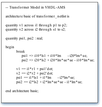
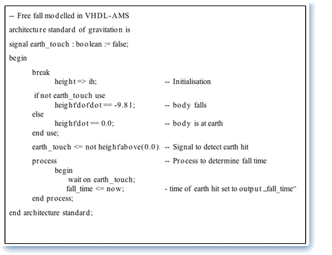
The modelling language VHDL-AMS is a standard (1076.1) set by the IEEE for the modelling of digital, analogue and “mixed-signal” (analogue-digital) systems. Models written in VHDL-AMS can be handled by a number of simulators which allows for model exchange even if project partners use different simulation software. The language is based on the standard VHDL which has been established for many years. VHDL allows for the description of the logic in digital (event-triggered) systems and provides a base for their synthetization. Now with the extension to VHDL-AMS, algebraic and differential equation systems may also be included.
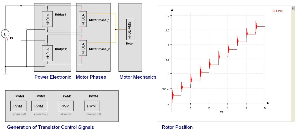
The combination of both modelling approaches results in a highly flexible modelling system. For example, the modelling of control parts can be carried out to a lower level of detail in a digital model, while motors, power electronics, mechanical parts and other components are described in more detail by algebraic and differential equations in an analogue model. The picture above demonstrates the capabilities of VHDL-AMS in the example of a stepper motor drive. The system simulation consists of a number of component models, all of them written in VHDL-AMS. The motor is controlled by an inverter made of two H-bridges. PWM signals for switching the transistors on and off are generated by digital processes. The models of the inverter (electrical), motor phases (electrical/mechanical) and rotor (mechanical) use analogue statements only. This simulation model has been created by Adapted Solutions in the frame of a project run by the FAT working group Simulation of mixed-signal systems with VHDL-AMS.
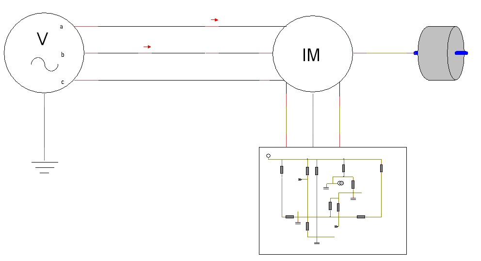
The adjacent picture shows the linking of several domains by a VHDL-AMS model. The simulation is built of models for a three-phase voltage source, an induction machine and its mechanical load. The model of the induction machine is split into two parts. The equation set that describes the electro-magnetic interactions, the generation of the torque and the rotor movement is given in a VHDL-AMS model. This model includes pins to link it with electrical, mechanical and thermal networks. Thermal conditions inside the machine are calculated by a sub-sheet which is linked to the VHDL-AMS model. Via its thermal pins, the VHDL-AMS model feeds the losses of the machine into the thermal network. Vice versa, it may read the node temperatures and re-calculated the temperature-dependent parameters of the electro-magnetic network.
The usage of a description language offers advantages compared to graphical modelling, particularly when bigger equation sets have to be implemented as in electrical machines. Text book equations may be converted into model lines very conveniently.
The entity-architecture concept used by VHDL-AMS offers the possibility to assign several behaviour descriptions (“architectures”) to the same model having a defined interface (“entity”). Due to this feature, alternative equation sets of different complexities may be implemented and chosen depending on the requirements of a particular simulation.
In Portunus, VHDL-AMS models can be created with the help of a powerful editor or simply read from ASCII files. The editor features functions like syntax colouring and allows for an immediate check of the model text for correct syntax. A symbol editor allows for an adaptation of the symbol in the schematic. VHDL-AMS models may be stored and edited in the schematic or in a library.
Magnetic
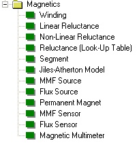
Many systems contain components with magnetic materials. Such elements can be modelled in different ways. Quite often the magnetic properties have an influence on the model behaviour via the set (constant or load-dependent) inductance values. A more detailed investigation of the values of the magnetic circuit is possible by building up separate networks. For this, Portunus comes with a number of models.
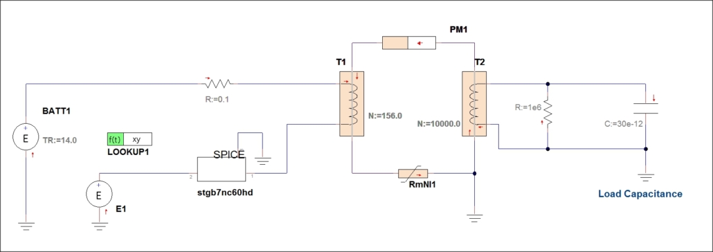
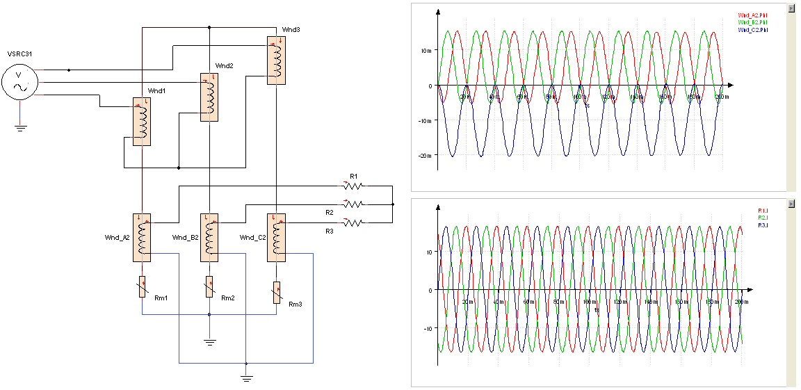
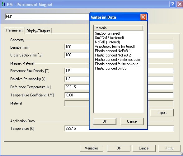
Magnetic networks may be coupled to the electrical ones by a winding model. If the user wishes to ignore electrical components, magnetic sources (magneto-motive force, magnetic flux) and a permanent magnet model can be used. Reluctances can be defined by constants and expressions, look-up tables or by using the non-linear Jiles-Atherton core model. Input dialogs of most of the magnetic models provide the option of calculating model parameters from geometry and material data. A table import is provided for the most important magnetic materials. If the requirements of the models cannot be met by the library components, specific models can be created by using VHDL-AMS or the C++ programming interface.
The magnetic models integrated in Portunus support all analysis types. The only exception is the Jiles-Atherton core model which supports transient analysis only.
Automated C Code Generation out of VHDL-AMS Models
A tool for the automated generation of C code out of VHDL-AMS models is being developed at the West Saxon University of Applied Sciences of Zwickau. This work is carried out in the frame of a project supported by the German Federal Ministry of Education and Research (funding reference 1767X09). The VHDL-AMS models are developed with the help of Portunus.
One of the project goals is to demonstrate an alternative to the nowadays common practice of code generation. At present, code generation is usually based on block diagrams which represent the technical process at a high abstraction level (often from the point of view of the control engineer only). This approach may reflect the electronic or mechatronic aspects of the systems only rudimentally. The same applies for the test of the automatically generated software (e.g. with the help of Hardware-in-the-Loop systems), unless this test is done by using test tools (emulators).
The alternative to this approach is related to the model description language VHDL-AMS which is supported by Portunus. It allows for a much more effective modelling and simulation of digital, analogue and mixed-signal systems made of electrical and non-electrical components. VHDL-AMS fulfils requirement as they are especially present in power electronics, regenerative energy systems, automotive applications, aviation, aerospace and medical systems.
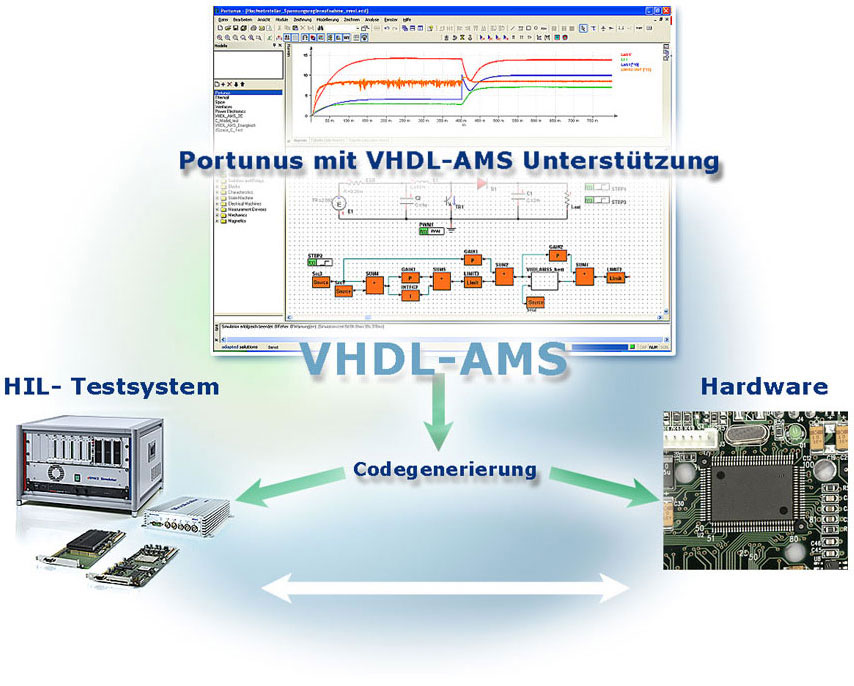
The code generator developed in this project allows for the automated conversion of VHDL-AMS models handled by Portunus into C code which may run in real time at different micro-controller and signal processor platforms. A hardware-in-the-loop link (dSPACE) has been tested successfully too.
The code generator is based on a Portunus library containing VHDL-AMS models for the syn-thesis of complex system models. This part of the system model that describes the control can be automatically converted into C code.
Further Information
West Saxon University of Applied Sciences of Zwickau
Publications (German)
- Modellkonzept eines dualen Energiespeichersystems für elektromobile Anwendungen
Michael Wittig, Sven Slawinski, Rene Jost, Lutz Zacharias, Mirko Bodach
21. Internationale Wissenschaftliche Konferenz 26.-27. Oktober 2011, Mittweida
Hochschule Mittweida , Journal Scientific Reports, ISSN 1437-7624 - Optimierung des Steuerelektronik-Entwicklungsablaufs durch automatisierte Softwareentwicklung mit Hilfe von VHDL-AMS
Sven Slawinski, Lutz Zacharias, Mirko Bodach, Thomas Barucki
21. Internationale Wissenschaftliche Konferenz 26.-27. Oktober 2011, Mittweida
Hochschule Mittweida , Journal Scientific Reports, ISSN 1437-7624

